Router Placement, Wall Materials, and Why Your Smart Home Has Signal Dead Zones
A smart home with twenty or thirty connected devices is a different RF environment than a home with a laptop and a phone. Every device — the thermostat, the door lock, the ceiling light, the security camera — depends on a consistent wireless connection to function reliably. When the signal is good, the system works seamlessly and seems effortless. When coverage is uneven and dead zones exist, the same system generates frustrating intermittent failures: a light that won’t respond, a camera that goes offline, a lock that takes five seconds to report its status. The difference between these two outcomes is often antenna placement and an understanding of how the home’s physical structure shapes the signal.
How building materials attenuate Wi-Fi signals
Wi-Fi signals travel through air with minimal loss. They travel through building materials with varying degrees of attenuation depending on the material’s composition and thickness. Understanding which materials in a home cause the most signal loss is the starting point for identifying why certain rooms or areas have poor coverage.
Glass and drywall are relatively transparent to Wi-Fi — a signal passing through a standard interior drywall partition loses only a few decibels of signal strength. Wood has similar characteristics. These materials are not the source of most dead zone problems.
Concrete and brick are significantly more absorptive. A concrete floor or exterior wall can attenuate a 2.4 GHz signal by 10–15 dB, which translates to a substantial reduction in signal strength and reliability. Homes with concrete construction between floors, or with brick exterior walls, have inherently higher signal loss between different levels and between interior and exterior spaces.
Metal is the most significant attenuator. Metal studs in wall construction, foil-faced insulation, metallic wallpaper or tile backer, and large metal objects — filing cabinets, appliances, steel doors — all block or reflect Wi-Fi signals in ways that create shadows. The shadow effect is directional: a metal filing cabinet doesn’t weaken the signal uniformly in all directions, it creates a specific area behind it relative to the router where signal is poor.
The router’s antenna position and what it actually covers
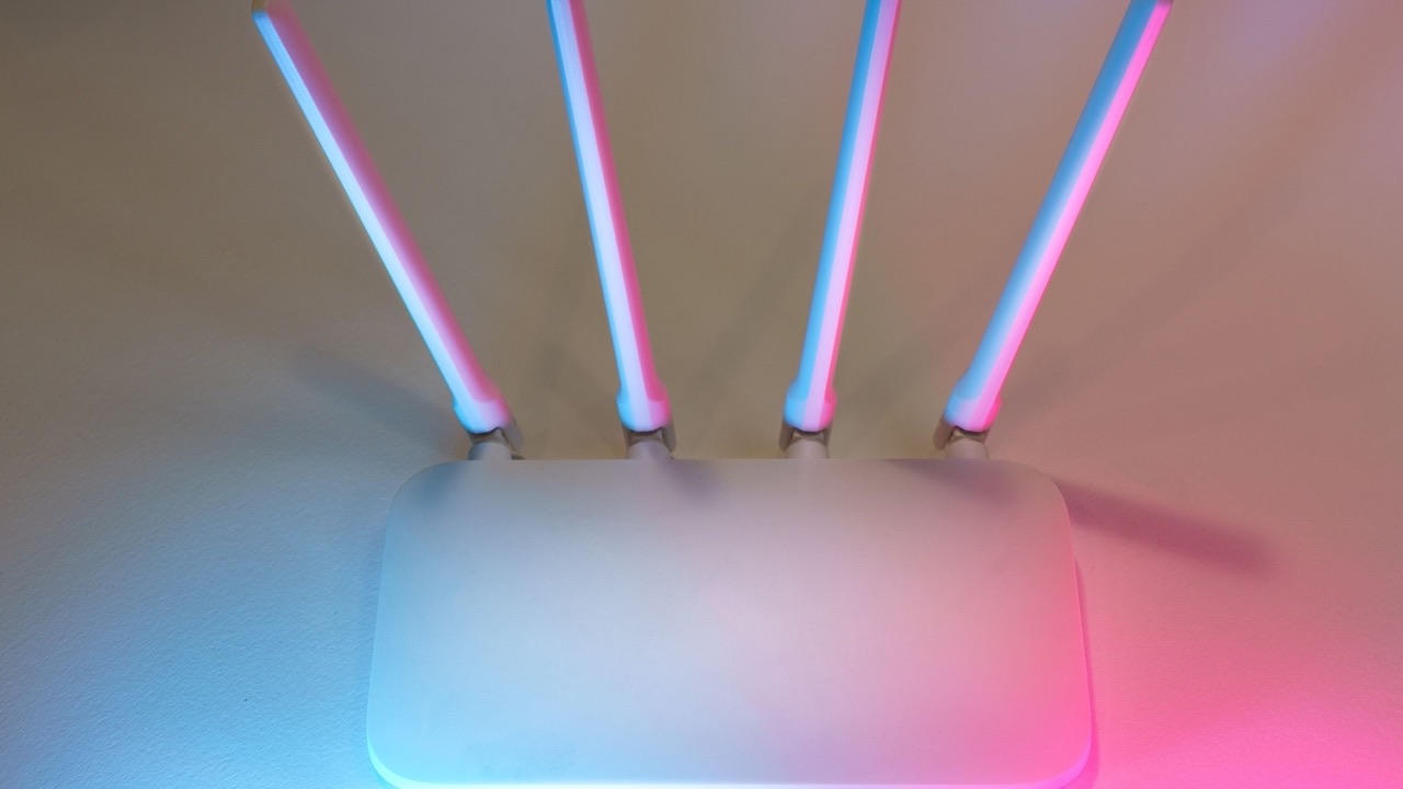
A router’s internal or external antennas radiate in a pattern that resembles the toroidal shape of a dipole: strong in the horizontal plane around the antenna, weaker directly above and below it. This means a router with vertically oriented antennas provides good horizontal coverage — across a room, to an adjacent room on the same floor — but covers the floor above and below less effectively.
Placing a router in a corner of a room covers two walls adequately and two walls poorly. The signal radiates outward from the router’s position, and walls that are behind the router relative to the coverage area it needs to reach receive a weaker signal than walls the router is pointing toward. Central placement — in the middle of the floor being covered — distributes the signal more evenly in all directions.
Elevation matters too. A router placed on the floor sends most of its signal into the floor and ceiling, which is wasted. A router at mid-room height — on a shelf or mounted on a wall at roughly chest height — maximizes coverage in the occupied areas of the room.
Multi-floor coverage and why it’s harder than it looks
Covering multiple floors with a single router is fundamentally a geometry problem. The router’s antenna pattern has lower gain toward the floor and ceiling than toward the walls, and there’s a concrete or wood floor assembly between levels. The result is that upper and lower floors typically receive a weaker signal than the same floor as the router.
The router placement that maximizes multi-floor coverage is on the intermediate floor if there are three levels, positioned toward the center of the floor plan. This minimizes the distance and number of floor assemblies the signal has to penetrate in either direction. For a two-floor home, a router on the upper floor covers downward more reliably than one on the lower floor covers upward, because the upper floor router’s downward-radiating pattern points into the occupied space below.
External antennas on the router offer some ability to adjust coverage direction. Tilting antennas to 45 degrees changes the radiation pattern to include more vertical coverage alongside horizontal. For a router on the ground floor of a two-story home, antennas angled at 45 degrees cover the upper floor better than fully vertical antennas, at the cost of some horizontal range on the same floor.
Smart home device placement and its effect on antenna performance
Smart home devices have their own antennas, and where those devices are placed affects how well they connect to the router. A smart plug installed behind a metal appliance sits in that appliance’s RF shadow. A smart thermostat mounted on an exterior wall near a foil-faced insulation cavity has a wall full of reflective material between it and the router. A camera installed in a metal electrical box has its antenna surrounded by a conductor.
The cumulative effect of poor device placement is a network where some devices connect reliably while others intermittently lose connection, creating a troubleshooting problem that looks like a protocol or firmware issue but is actually a coverage geometry issue. Identifying which devices have inconsistent connections and mapping their locations relative to the router and the building’s material composition usually reveals a pattern that points to a placement fix rather than a hardware fix.
Where Smart Home Antennas fit into the coverage solution
For routers and access points with external antenna connectors, upgrading the antennas changes the radiation pattern and can address specific coverage problems. A high-gain directional antenna pointed toward a problem area increases signal in that direction at the cost of reduced coverage in other directions. A panel antenna mounted on a wall and aimed down a hallway provides strong coverage along the hallway with minimal wasted signal going through walls that don’t need coverage.
This approach works best when the problem is a specific location that isn’t covered by the existing omnidirectional antenna pattern — a detached garage, a basement room on the far side of a concrete wall, an outdoor area adjacent to the house. Replacing the router’s stock omnidirectional antenna with a panel antenna aimed at the specific problem location can resolve coverage issues that adding a mesh node wouldn’t efficiently address.
The prerequisite is a router or access point with standard antenna connectors — typically SMA or RP-SMA — that accepts external antennas. Many consumer routers have fixed internal antennas that can’t be replaced. Routers designed for more flexible deployment, including those used in small business or prosumer environments, more commonly have external antenna connectors that allow the coverage pattern to be adjusted for the specific installation.
When mesh networking is the right answer instead
Antenna optimization works within the constraints of a single access point’s coverage range. When the coverage problem is fundamentally a distance problem — the home is large enough that no single access point can cover it adequately regardless of antenna placement — additional access points are more effective than antenna upgrades.
Mesh systems place multiple access points throughout the home and handle the routing between them automatically. The antenna optimization principles still apply to each mesh node: central placement on each floor, away from metal obstructions, at mid-room height. A well-placed mesh system with standard antennas outperforms a poorly placed system with high-gain antennas, because signal strength and coverage consistency depend on geometry first and antenna specification second.